Spanning from electronic DESIGN to the SALE of electronic components.
Two series, 10 categories and 120 part numbers — the passives that filter and store, the actives that switch and protect. Every line item is held or sourced factory-original, inspected in batch, and shipped with full traceability.
Series 01
Passive Components
Inductors, capacitors, resistors and timing devices — the parts that filter, store and stabilise every rail in your design.
5 categories60 part numbersFactory-originalBatch inspected
01.1
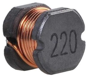
Power Inductor
Chip power inductors, also known as high-current inductors, sit in series with the supply rail: they pass DC and present high impedance to high-frequency pulses. Low DC resistance and a high rated current are achieved through a unique winding structure, so the part stays cool at full load.
Surface mountLow DC resistanceReflow compatible
LPI-0412-1R0M
Inductance1.0 µH
I rated3.2 A
DCR45 mΩ
Size: 4.0 × 4.0 × 1.2 mmLPI-0412-2R2M
Inductance2.2 µH
I rated2.4 A
DCR72 mΩ
Size: 4.0 × 4.0 × 1.2 mmLPI-0518-4R7M
Inductance4.7 µH
I rated2.8 A
DCR60 mΩ
Size: 5.0 × 5.0 × 1.8 mmLPI-0518-100M
Inductance10 µH
I rated1.9 A
DCR105 mΩ
Size: 5.0 × 5.0 × 1.8 mmLPI-0620-220M
Inductance22 µH
I rated1.4 A
DCR165 mΩ
Size: 6.0 × 6.0 × 2.0 mmLPI-0620-470M
Inductance47 µH
I rated0.95 A
DCR320 mΩ
Size: 6.0 × 6.0 × 2.0 mmLPI-0824-101M
Inductance100 µH
I rated0.72 A
DCR520 mΩ
Size: 8.0 × 8.0 × 2.4 mmLPI-0824-221M
Inductance220 µH
I rated0.48 A
DCR1.05 Ω
Size: 8.0 × 8.0 × 2.4 mmLPI-1040-150M
Inductance15 µH
I rated4.5 A
DCR32 mΩ
Size: 10 × 10 × 4.0 mmLPI-1040-330M
Inductance33 µH
I rated3.1 A
DCR55 mΩ
Size: 10 × 10 × 4.0 mmLPI-1265-680M
Inductance68 µH
I rated2.6 A
DCR88 mΩ
Size: 12 × 12 × 6.5 mmLPI-1265-151M
Inductance150 µH
I rated1.7 A
DCR190 mΩ
Size: 12 × 12 × 6.5 mm
01.2
Multilayer Chip Inductor
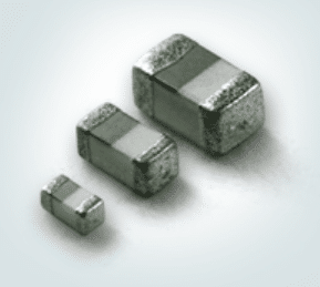
Chip inductors, also known as surface-mount inductors, are the leadless miniature components built for Surface Mount Technology, exactly like other chip components. A multilayer ceramic body keeps them compact while holding a stable inductance across the operating temperature range.
0402 – 1206High QLead-free
MLZ-1005-1N0S
Inductance1.0 nH
Tolerance±0.3 nH
I rated0.9 A
Case: 0402MLZ-1005-2N2S
Inductance2.2 nH
Tolerance±0.3 nH
I rated0.8 A
Case: 0402MLZ-1005-4N7J
Inductance4.7 nH
Tolerance±5%
I rated0.7 A
Case: 0402MLZ-1005-100J
Inductance10 nH
Tolerance±5%
I rated0.6 A
Case: 0402MLZ-1608-22NJ
Inductance22 nH
Tolerance±5%
I rated0.5 A
Case: 0603MLZ-1608-47NJ
Inductance47 nH
Tolerance±5%
I rated0.4 A
Case: 0603MLZ-1608-100K
Inductance100 nH
Tolerance±10%
I rated0.35 A
Case: 0603MLZ-1608-220K
Inductance220 nH
Tolerance±10%
I rated0.3 A
Case: 0603MLZ-2012-470K
Inductance470 nH
Tolerance±10%
I rated0.3 A
Case: 0805MLZ-2012-101K
Inductance1.0 µH
Tolerance±10%
I rated0.25 A
Case: 0805MLZ-2012-221K
Inductance2.2 µH
Tolerance±10%
I rated0.2 A
Case: 0805MLZ-3216-471K
Inductance4.7 µH
Tolerance±10%
I rated0.15 A
Case: 1206
01.3
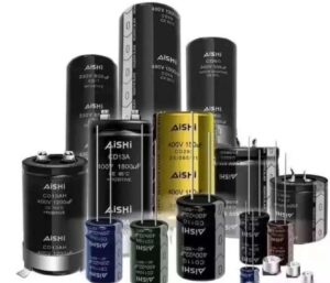
Aluminum Electrolytic Capacitor
Large capacitance in a small can, with high ripple handling and a low unit cost. The trade-off is leakage current, finite life and strict polarity, which makes these parts the natural choice for power filtering and low-frequency circuits.
PolarisedPower filtering105 °C rated
AEC-0505-100M
Capacitance10 µF
Voltage50 V
Ripple45 mA
Case: 5 × 11 mmAEC-0355-220M
Capacitance22 µF
Voltage35 V
Ripple60 mA
Case: 5 × 11 mmAEC-0255-330M
Capacitance33 µF
Voltage25 V
Ripple75 mA
Case: 5 × 11 mmAEC-0256-470M
Capacitance47 µF
Voltage25 V
Ripple95 mA
Case: 6.3 × 11 mmAEC-0256-101M
Capacitance100 µF
Voltage25 V
Ripple140 mA
Case: 6.3 × 11 mmAEC-0168-221M
Capacitance220 µF
Voltage16 V
Ripple220 mA
Case: 8 × 12 mmAEC-0258-331M
Capacitance330 µF
Voltage25 V
Ripple280 mA
Case: 8 × 12 mmAEC-025D-471M
Capacitance470 µF
Voltage25 V
Ripple380 mA
Case: 10 × 13 mmAEC-016G-102M
Capacitance1000 µF
Voltage16 V
Ripple550 mA
Case: 10 × 16 mmAEC-025M-222M
Capacitance2200 µF
Voltage25 V
Ripple900 mA
Case: 13 × 21 mmAEC-035P-472M
Capacitance4700 µF
Voltage35 V
Ripple1.35 A
Case: 16 × 26 mmAEC-050V-103M
Capacitance10000 µF
Voltage50 V
Ripple2.1 A
Case: 22 × 36 mm
01.4
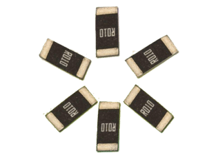
Chip Resistor
Thick-film chip resistors from 0201 to 2512, with a boosted power series for the same footprint. Standard tolerance is ±1%, and every case size below carries its own maximum working voltage so you can derate with confidence.
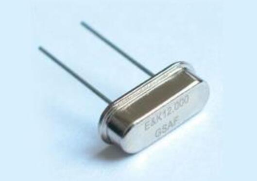
Packaged timing references from 32.768 kHz up to 100 MHz, in 2016, 3225, 5032 and 7050 footprints. CMOS output, ±10 ppm stability options and low phase noise make them suitable for both RTC keep-alive and high-speed digital clocking.
3225 / 5032 / 7050±10 ppmCMOS output
XO-2016-32.768K
Frequency32.768 kHz
Stability±20 ppm
Load12.5 pF
Package: 2.0 × 1.6 mmXO-3225-8.000M
Frequency8 MHz
Stability±10 ppm
Load15 pF
Package: 3.2 × 2.5 mmXO-3225-12.000M
Frequency12 MHz
Stability±10 ppm
Load15 pF
Package: 3.2 × 2.5 mmXO-3225-16.000M
Frequency16 MHz
Stability±10 ppm
Load15 pF
Package: 3.2 × 2.5 mmXO-3225-24.000M
Frequency24 MHz
Stability±10 ppm
Load15 pF
Package: 3.2 × 2.5 mmXO-3225-25.000M
Frequency25 MHz
Stability±10 ppm
Load15 pF
Package: 3.2 × 2.5 mmXO-5032-8.000M
Frequency8 MHz
Stability±10 ppm
Load15 pF
Package: 5.0 × 3.2 mmXO-5032-25.000M
Frequency25 MHz
Stability±10 ppm
Load15 pF
Package: 5.0 × 3.2 mmXO-5032-27.000M
Frequency27 MHz
Stability±10 ppm
Load15 pF
Package: 5.0 × 3.2 mmXO-5032-48.000M
Frequency48 MHz
Stability±10 ppm
Load15 pF
Package: 5.0 × 3.2 mmXO-7050-25.000M
Frequency25 MHz
Stability±10 ppm
Load15 pF
Package: 7.0 × 5.0 mmXO-7050-100.000M
Frequency100 MHz
Stability±10 ppm
Load15 pF
Package: 7.0 × 5.0 mm
Series 02
Active & Protection
Switching, rectifying and clamping devices that carry the load current and absorb the surge before it reaches your circuit.
5 categories60 part numbersFactory-originalBatch inspected
02.1
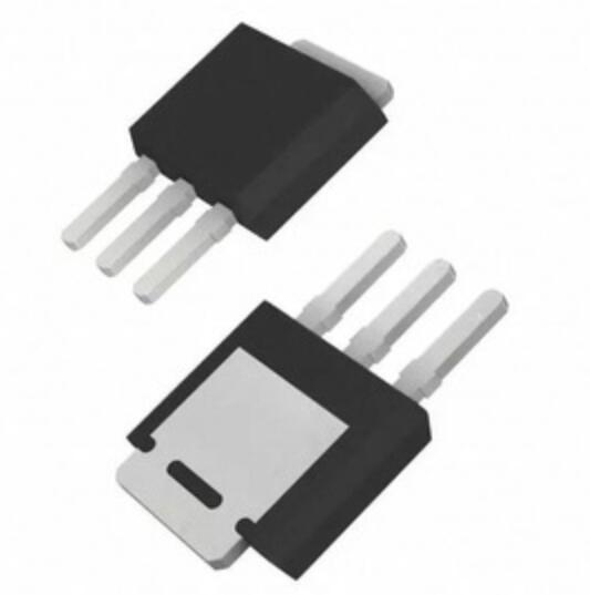
MOSFET
N-channel power MOSFETs from 30 V logic-level parts up to 650 V high-voltage switches. Low RDS(on) in DFN and TO packages keeps conduction loss down, while the avalanche-rated cells survive the transients that switching supplies throw at them.
30 – 650 VLow RDS(on)Avalanche rated
LMT-30N30
VDS30 V
ID30 A
RDS(on)6.5 mΩ
Package: DFN 5 × 6LMT-30N60
VDS30 V
ID60 A
RDS(on)3.2 mΩ
Package: DFN 5 × 6LMT-40N50
VDS40 V
ID50 A
RDS(on)5.0 mΩ
Package: TO-252LMT-60N30
VDS60 V
ID30 A
RDS(on)12 mΩ
Package: TO-220LMT-60N60
VDS60 V
ID60 A
RDS(on)8.0 mΩ
Package: TO-220LMT-80N45
VDS80 V
ID45 A
RDS(on)14 mΩ
Package: TO-247LMT-100N50
VDS100 V
ID50 A
RDS(on)18 mΩ
Package: TO-247LMT-150N20
VDS150 V
ID20 A
RDS(on)65 mΩ
Package: TO-220LMT-200N15
VDS200 V
ID15 A
RDS(on)110 mΩ
Package: TO-247LMT-500N05
VDS500 V
ID5 A
RDS(on)1.2 Ω
Package: TO-220LMT-600N08
VDS600 V
ID8 A
RDS(on)0.85 Ω
Package: TO-247LMT-650N04
VDS650 V
ID4 A
RDS(on)1.8 Ω
Package: TO-252
02.2
Schottky Diode
Instead of a PN junction, the Schottky barrier diode is built on a metal-semiconductor contact. There is no minority carrier storage, so it switches off with no reverse recovery tail — the reason it dominates the freewheeling path of switching supplies.
20 – 200 VLow VFNo reverse recovery
LSD-20-1A
VRRM20 V
IF1 A
VF0.45 V
Package: SOD-123LSD-40-3A
VRRM40 V
IF3 A
VF0.55 V
Package: SMALSD-40-5A
VRRM40 V
IF5 A
VF0.55 V
Package: SMBLSD-45-8A
VRRM45 V
IF8 A
VF0.58 V
Package: SMCLSD-60-3A
VRRM60 V
IF3 A
VF0.62 V
Package: SMALSD-60-10A
VRRM60 V
IF10 A
VF0.65 V
Package: TO-220LSD-100-5A
VRRM100 V
IF5 A
VF0.72 V
Package: SMBLSD-100-15A
VRRM100 V
IF15 A
VF0.75 V
Package: TO-247LSD-100-30A
VRRM100 V
IF30 A
VF0.80 V
Package: TO-247LSD-150-2A
VRRM150 V
IF2 A
VF0.85 V
Package: SMBLSD-150-30A
VRRM150 V
IF30 A
VF0.88 V
Package: TO-247LSD-200-10A
VRRM200 V
IF10 A
VF0.95 V
Package: TO-247
02.3
TVS Diode
Connected in parallel with the circuit it protects, the TVS conducts within nanoseconds when an overvoltage arrives and shunts the surge away, then resets automatically. Response is faster than a varistor or a gas discharge tube, which is why it sits closest to the connector.
400 – 3000 WUni / bi-directionalSub-ns response
LTV-05-400
VRWM5 V
VBR min6.4 V
Ppk400 W
Package: SMALTV-05-600
VRWM5 V
VBR min6.4 V
Ppk600 W
Package: SMBLTV-08-1000
VRWM8 V
VBR min8.9 V
Ppk1000 W
Package: SMBLTV-12-600
VRWM12 V
VBR min13.3 V
Ppk600 W
Package: SMBLTV-12-3000
VRWM12 V
VBR min13.3 V
Ppk3000 W
Package: TO-247LTV-15-600
VRWM15 V
VBR min16.7 V
Ppk600 W
Package: SMBLTV-18-1500
VRWM18 V
VBR min20.0 V
Ppk1500 W
Package: SMCLTV-24-600
VRWM24 V
VBR min26.7 V
Ppk600 W
Package: SMBLTV-24-1500
VRWM24 V
VBR min26.7 V
Ppk1500 W
Package: SMCLTV-33-400
VRWM33 V
VBR min36.7 V
Ppk400 W
Package: SMALTV-48-1500
VRWM48 V
VBR min53.3 V
Ppk1500 W
Package: SMCLTV-58-3000
VRWM58 V
VBR min64.4 V
Ppk3000 W
Package: TO-247
02.4
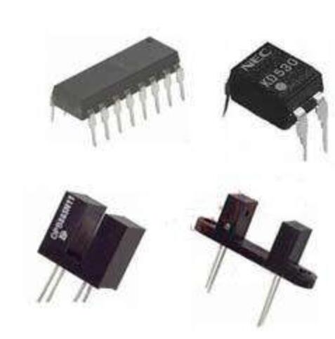
Optocoupler
An LED and a photodetector in one package, with nothing but light between them. That optical link is what carries the signal across the isolation barrier, keeping high-voltage transients and ground noise on the far side of your control circuit.
5.0 kVrmsCTR 50 – 600%DIP / SOP
LOC-817-A
CTR50 – 600%
Isolation5.0 kVrms
Channels1
Package: DIP-4LOC-817-B
CTR80 – 160%
Isolation5.0 kVrms
Channels1
Package: DIP-4LOC-817-C
CTR160 – 320%
Isolation5.0 kVrms
Channels1
Package: DIP-4LOC-817-D
CTR300 – 600%
Isolation5.0 kVrms
Channels1
Package: DIP-4LOC-817-2
CTR50 – 600%
Isolation5.0 kVrms
Channels2
Package: DIP-8LOC-817-4
CTR50 – 600%
Isolation5.0 kVrms
Channels4
Package: DIP-16LOC-357
CTR100 – 200%
Isolation3.75 kVrms
Channels1
Package: SOP-4LOC-357-2
CTR100 – 200%
Isolation3.75 kVrms
Channels2
Package: SOP-8LOC-521-1
CTR50 – 600%
Isolation5.0 kVrms
Channels1
Package: DIP-4LOC-1010
CTR100 – 300%
Isolation5.0 kVrms
Channels1
Package: SOP-4LOC-6N136
CTR1 Mbps
Isolation3.75 kVrms
Channels1
Package: DIP-8LOC-6N137
CTR10 Mbps
Isolation3.75 kVrms
Channels1
Package: DIP-8
02.5
IGBT
A MOSFET gate welded to a bipolar output stage: easy voltage drive on the input, low saturation loss on the output. Trench field-stop construction covers 600 V to 1700 V, for motor drives, induction heating and high-power inverters.
600 – 1700 VTrench field stopPositive VCE tempco
LIG-600-15
VCES600 V
IC15 A
VCE(sat)1.80 V
Package: TO-220LIG-600-30
VCES600 V
IC30 A
VCE(sat)1.90 V
Package: TO-247LIG-650-40
VCES650 V
IC40 A
VCE(sat)1.75 V
Package: TO-247LIG-650-60
VCES650 V
IC60 A
VCE(sat)1.85 V
Package: TO-247LIG-650-75
VCES650 V
IC75 A
VCE(sat)1.95 V
Package: TO-247LIG-650-100
VCES650 V
IC100 A
VCE(sat)1.90 V
Package: TO-247LIG-1200-15
VCES1200 V
IC15 A
VCE(sat)2.20 V
Package: TO-220LIG-1200-25
VCES1200 V
IC25 A
VCE(sat)2.10 V
Package: TO-247LIG-1200-40
VCES1200 V
IC40 A
VCE(sat)2.00 V
Package: TO-247LIG-1200-50
VCES1200 V
IC50 A
VCE(sat)2.05 V
Package: TO-247LIG-1700-25
VCES1700 V
IC25 A
VCE(sat)2.40 V
Package: TO-247LIG-1700-50
VCES1700 V
IC50 A
VCE(sat)2.30 V
Package: TO-247
Specifications shown are typical values for each series. Contact our engineering team for full datasheets, tolerance ranges, MOQ and current stock — or send your BOM for a free replacement and cost review.